electronics projects
I recently started toying around with microcontrollers and built a few simple things, mostly taking other people's projects as a starting point and morphing them into something that does the same thing, but worseWdifferent.
wireless temperature and humidity sensor with USB interface, version 2
this project is based on obdev's RemoteSensor example and their firmware-only USB implementation; the main change is the replacement of the analog sensors with a Sensirion SHT11 digital temperature and humidity sensor.
sensor unit
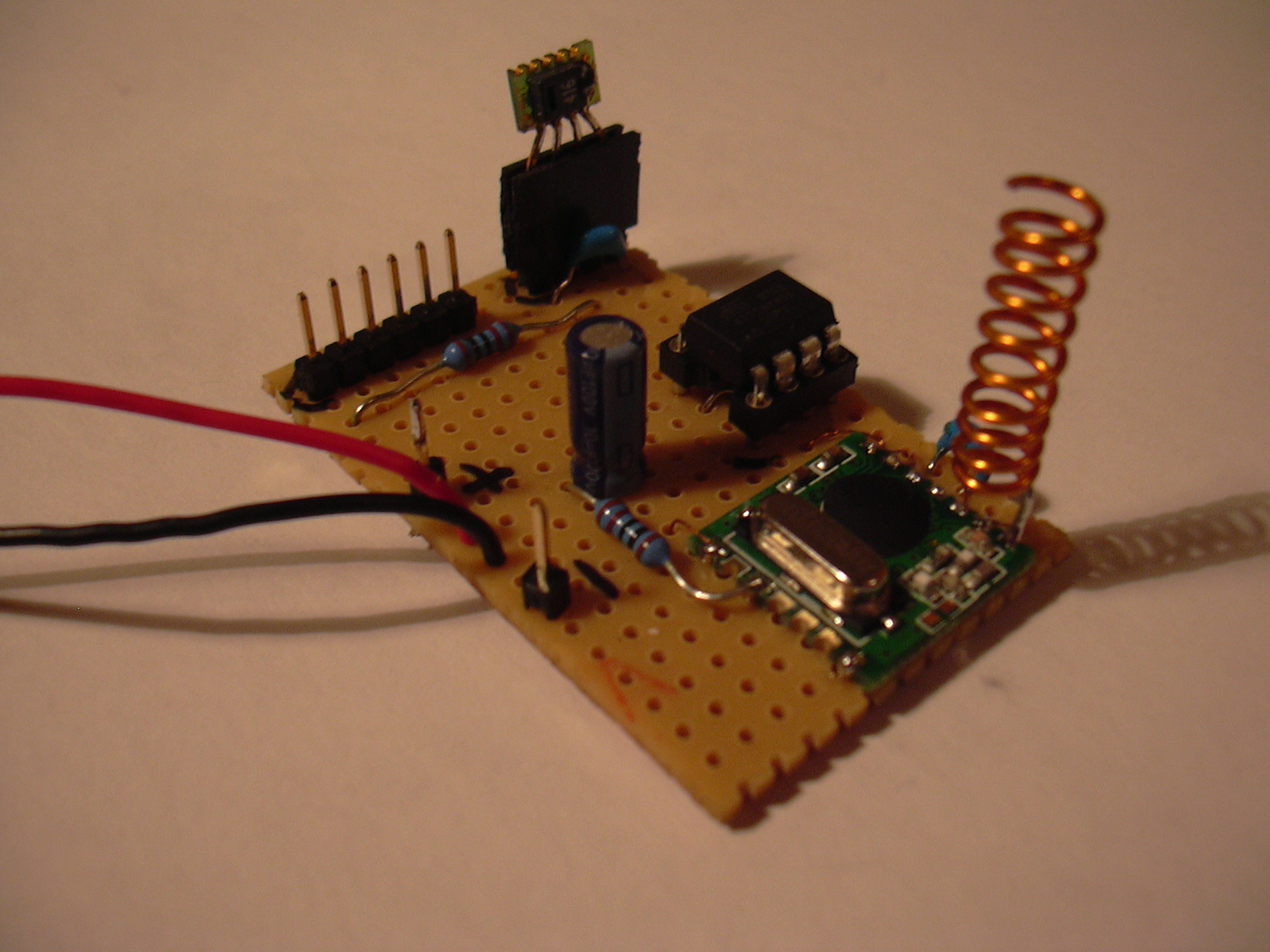
the sensor unit consists of an ATTiny45 microcontroller, a SHT11 sensor, and a hoperf RFM12 868 MHz transceiver module. it is powered by 2 AA cells and is expected to give >1 year of battery life.
receiver
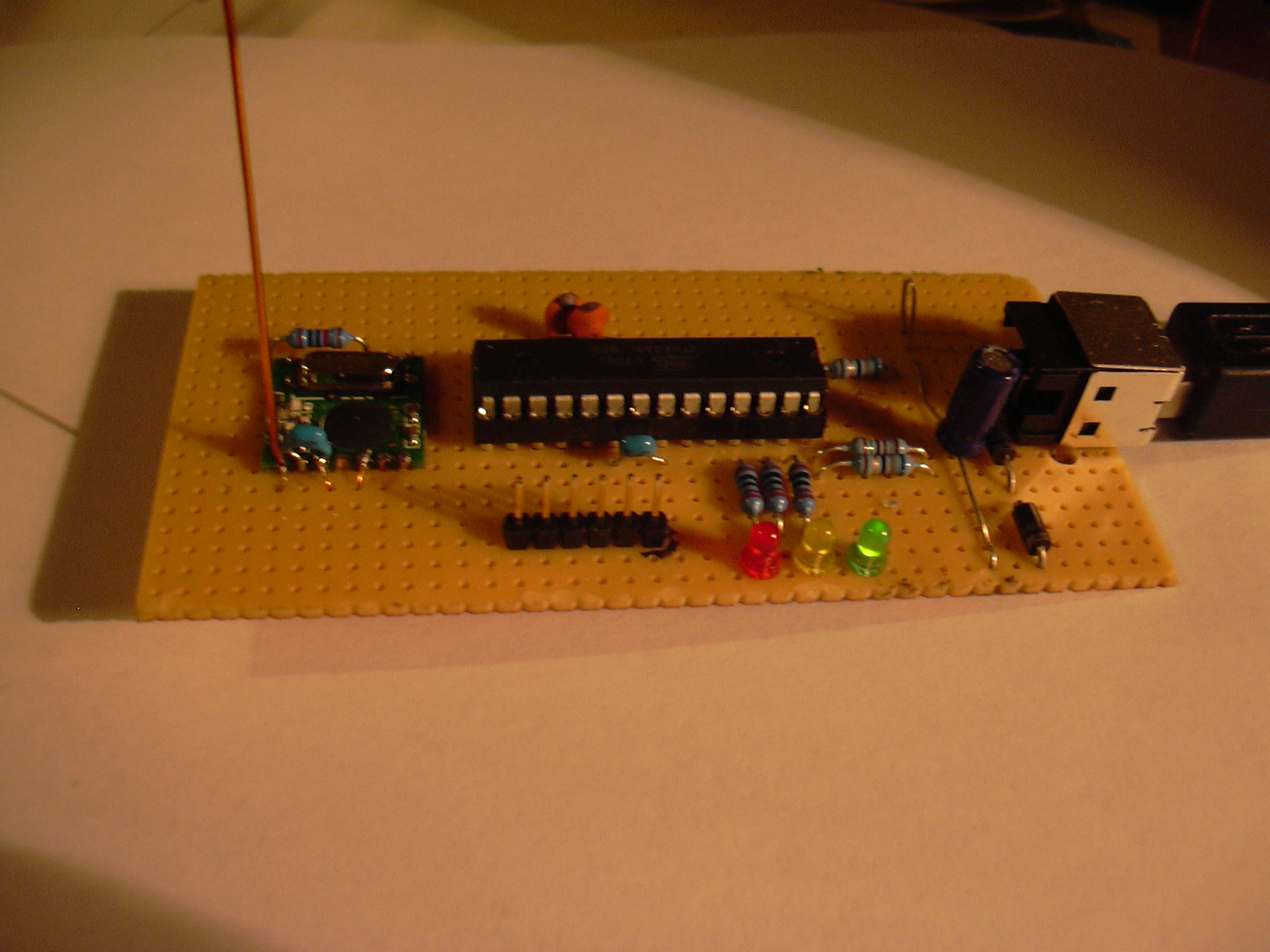
the receiver uses the same RFM12 module and an ATMega8 µC; received data is transmitted via USB to the PC.
host software
the host software can write out the received data in CSV format and in a one-line-per-value format for integration into the Cricket graphing system.
download
here's the tgz file with schematics (PNG and eagle) and software.
the old version (different hardware, worse software) can be found here.
brain machine
this is an improved version of Mitch Altman's Brain Machine.
the main improvements are:
- sine-wave audio
- arbitrary frequencies
- import of gnaural "schedule files" to define the sequences of brainwaves to be played
- selection between multiple stored sequences (planned)
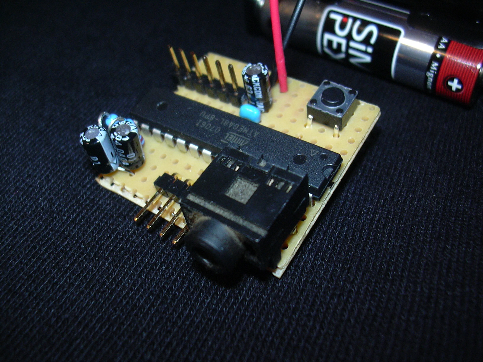
hardware
the hardware is based on an ATMega8, but this is just because I had that at hand. it uses only very few of the I/O ports -- two for audio, two for LEDs, one for a pushbutton, so it should be easy to use another controller that has an 8bit timer with two PWM channels (OCxA, OCxB).
add a piece of prototyping PCB, four capacitors, two resistors, a switch, connectors for headphones and glasses, and two AA cells, and you're done:
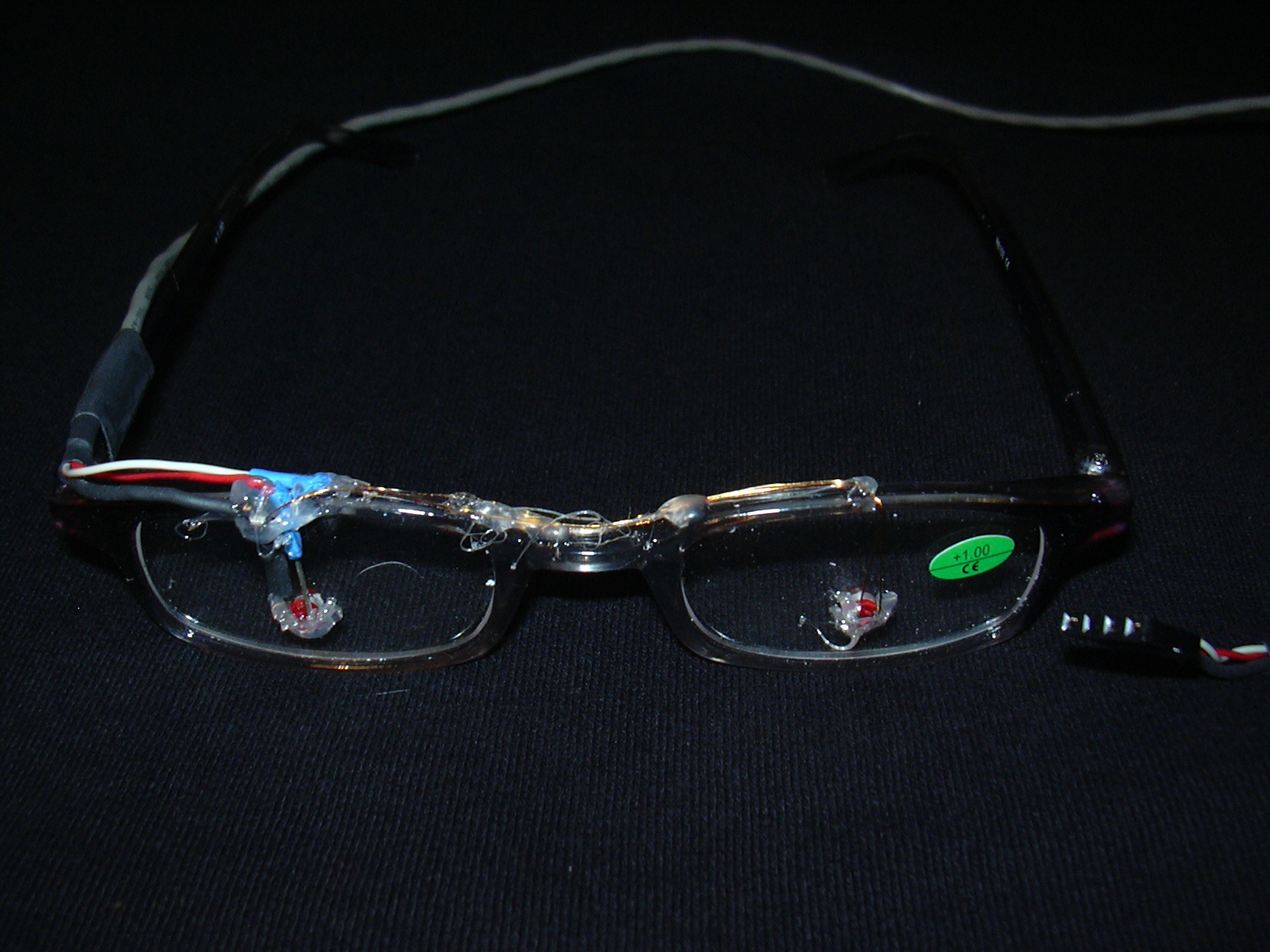
apropos glasses: I found a 3-pack of optical glasses at the supermarket for less than the cheapest protective goggles would have cost -- EUR 2.99. the "glass" in those is some kind of plastic which is easy to drill. the cable is a CD-ROM audio cable which you probably have around in your pile of computer stuff. hot glue, heat-shrink tubing, done:
general code layout
the code sets up interrupts on timer1 overflow, and all the DDS stuff happens in the ISR. the main code just waits for some volatile variables to change, iterates thru the sequence of brainwaves to be played and sets the DDS parameters accordingly.
if the sequence is done, the controller is put into power down sleep mode. when the button on INT0 is pressed, it wakes up and starts again. when the button is pressed while the machine is on, it turns off. sooner or later, I'll add code to allow selecting between different sequences.
DDS audio
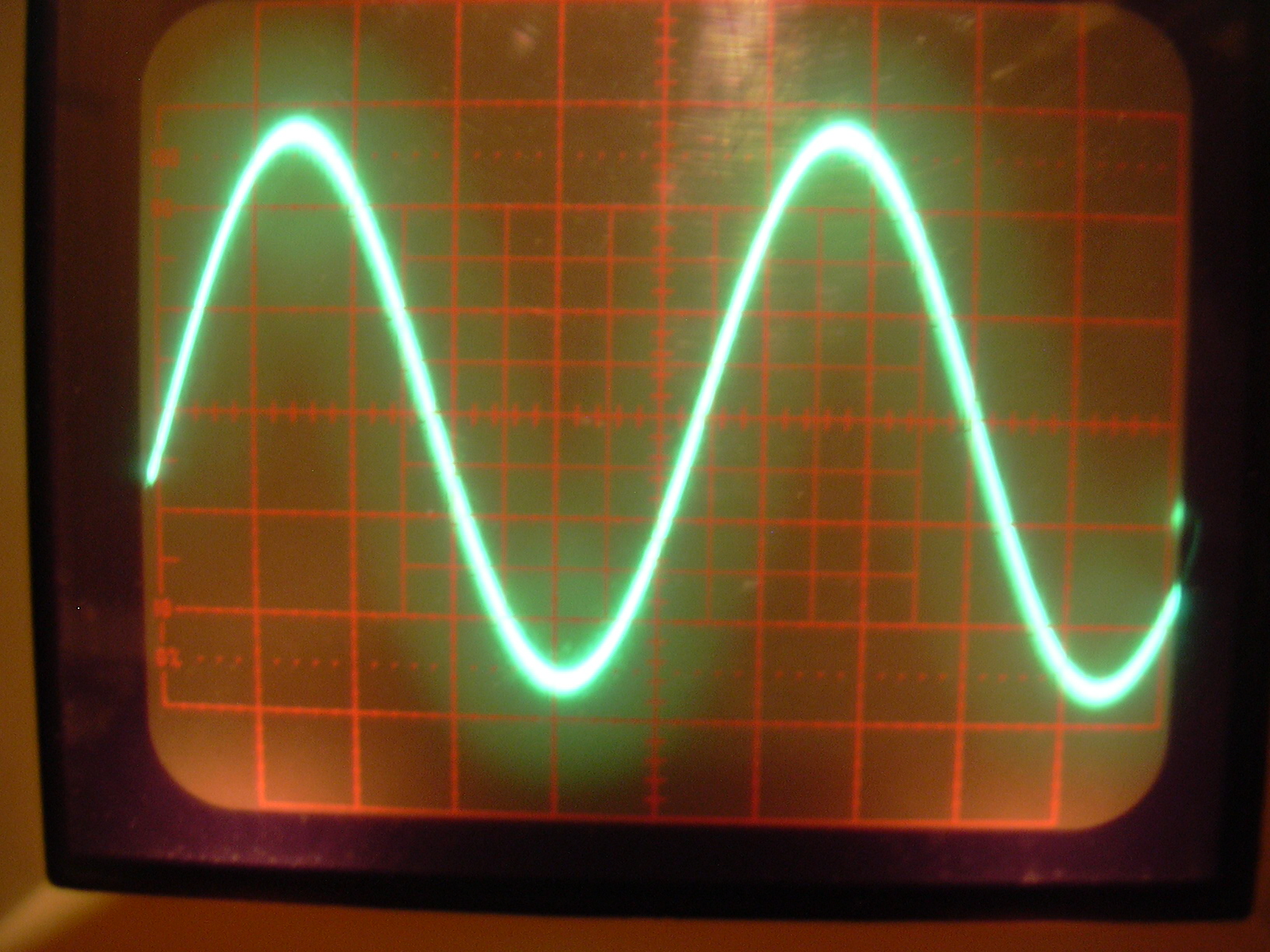
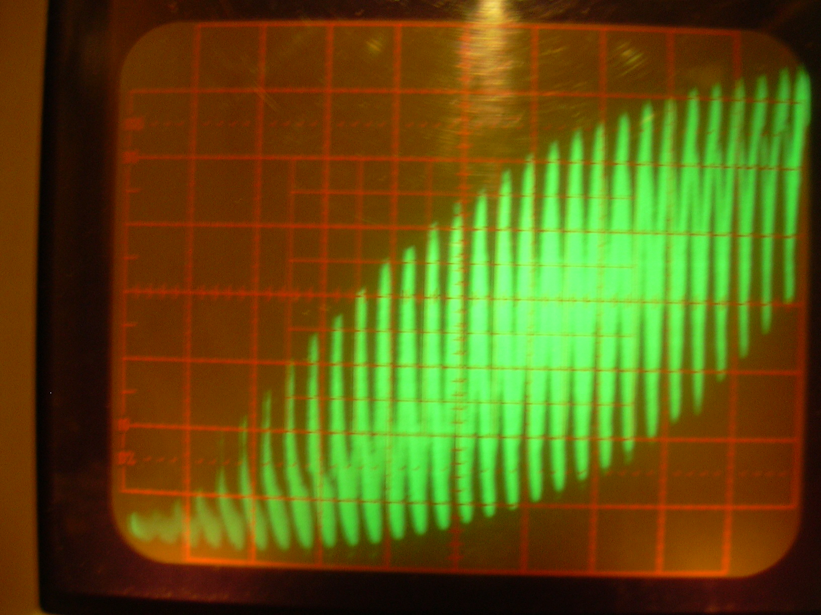
audio is DDS-generated sinewaves, pushed out by a PWM running at 15625Hz (8MHz CPU clock/512), lowpass-filtered by an RC network (2k2, 1µ) as in mitch's design. the resulting waveform is quite nice when viewed without headphones connected (first picture), but the PWM frequency shows when the inductance of the headphones comes into play (second picture). nonetheless, it sounds fine (or I'm getting too old to hear the 15625 Hz).
the DDS has a 256 value table which represents only 1/4 of a sine --
after all, the other 3/4 are symmetrical. a bit of bit fiddling (cf
magic in dds.h) handles this.
apropos dds.h: it's meant to be relatively independent of the rest
of the code, designed to be reusable. the data structures are designed
to be on byte boundaries for performance, which the C compiler doesn't
take advantage of (something to do with the C standard and the width
of bit-shifted types); it's fast enough for this application, but I
guess an assembler version would be at least 2x faster.
LED blinking
the LED blinking is tightly integrated with the DDS, no more timing loops. it's very simple: the LEDs should be synchronised to the binaural beat, which is the sum of the two audio channels. that sum is highest when the channels are in-phase (0°) and lowest when they're out-of-phase (180°), so we just take the difference of the phase accumulators and switch the LEDs according to the state of the most significant bit therein.
gnaural "schedule files"
gnaural is a program to generate binaural beats on the PC, and allows graphical editing of the respective frequency schedule. in the gnaural forums people post their favorite files.
since this is much nicer than coming up with sequences by myself, and hacking them into a text editor, I wrote a bit of perl to create data structures from those:
gnaural2slm.pl file1.gnaural file2.gnaural [...] > bwtab.h
recompile, flash the chip, done. at the moment, only the first of those schedules is played by the brain machine, but they all take up memory.
requirements
gcc for AVR, I'm using gcc 4.1 on linux.
avr-libc (I'm using 1.4.5)
perl and XML::Simple (for
gnaural2slm.pl)
download
download the project files here.