Convert an Olympus CH-2/CHT microscope to LED
This is specifically about the CHT model with the 30W/120V Tungsten bulb. I think the CHS/Halogen models have a different illumination path, YMMV.
My approach is completely reversible, no holes drilled in the base as some €500+ Ebay offers do.
BTW, the pictures on this page are clickable for full size.
Components
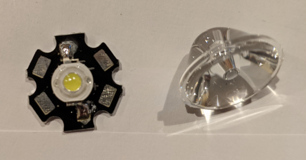
- 3W LED on a star PCB, I chose a 4000K "neutral white" one.
- LED lens, 15° works for me
- a buck converter with current limiting
- A power supply that does at least 7V DC
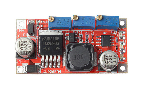
Buck converter
This LM2596 buck converter (I used the "three pot" version, but the two pot version would probably work as well) sets the reference voltage for the current limit from a 5V rail, then a 470kΩ resistor, and then the 10kΩ potentiometer.
That 5V rail is provided by a 78L05 on the converter board, which has a minimum input voltage of 7V.
The dirty trick
It turns out that the original, wire wound potentiometer in the scope has some 700Ω, and when you just replace the 10kΩ pot with it, max current turns out to be a bit more than 500mA. As the shunt on my buck converter is actually just a longer trace on the PCB, it might vary across models, and this might not work for you.
But -- this spared me the effort of trying to mount a standard 10kΩ pot in place of the original wire-wound one.
Steps
3D print the parts
The STLs and FreeCAD files are on YouMagine.
Print the LED-mount.stl from PETG (temperature and the tendency to creep make PLA suboptimal for this) and see whether your lens and LED fit.
The LED PCB should protrude a bit (1-2mm) from the bottom, that's by design. The mount will flex a bit when screwing it down and make sure there's pressure to keep the heat transfer from the PCB to the metal plate in the little door up.
The Buck-holder.stl is designed for a PCB size of approx 49mm x 25mm. PLA should be fine here.
Take it apart
Take the base off the scope, 4 M4 screws, 3 inside the rubber feet and one a bit to the side. Be careful when removing the plastic base, the grounding cable is attached to the metal part above.
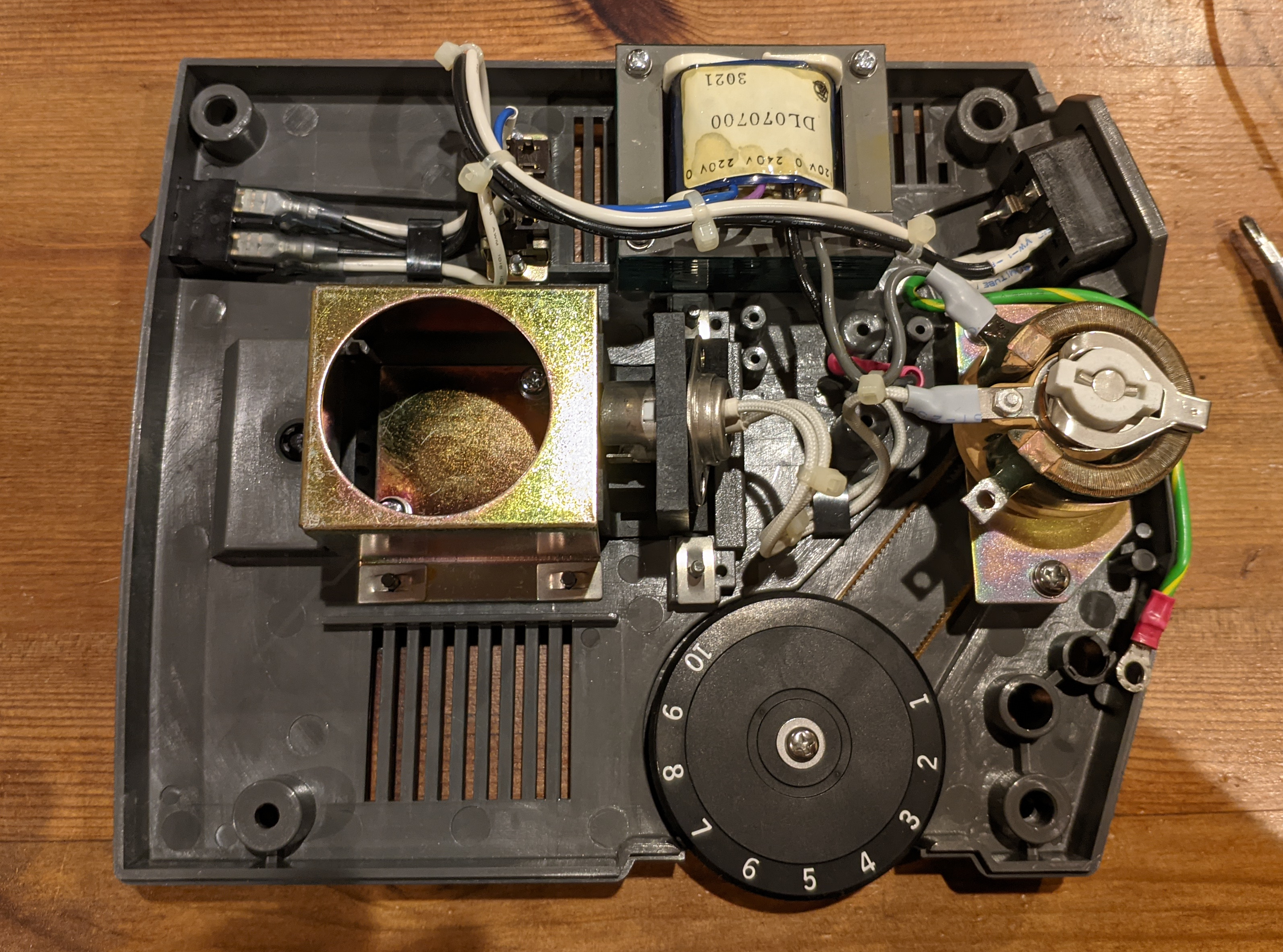
Remove some parts
I removed:
- The bulb and socket from the door
- The 220V/240V selector switch
- The transformer
![]()
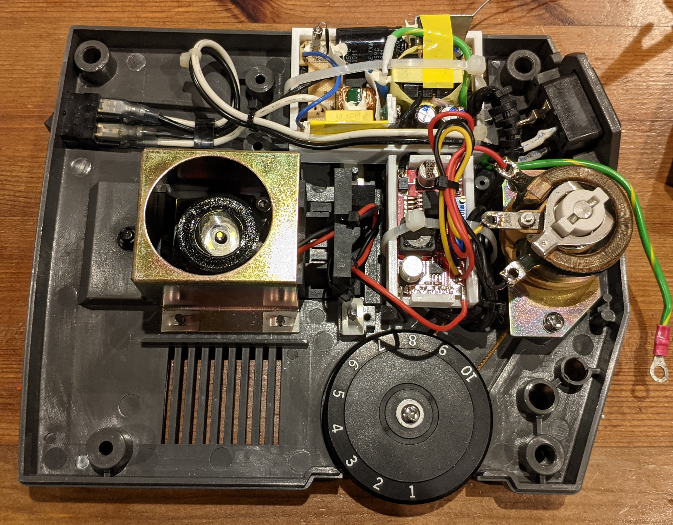
Add new parts
The LED holder with the lens and LED goes on top of the metal plate in the door.
Adding some thermal paste there definitely helps. At full power, the temperature doesn't go above 52°C.
Remove the current control pot from the buck converter, and connect the original pot in its place with some wires. Given the low voltages involved here (single-digit millivolts), keep the cables short.
Install the power supply if you have an adequately-sized one; I cracked open the case of a small 12V PSU and installed the naked board, but you better do what you feel comfortable with, after all, this could kill you. Maybe add a barrel connector and use an external wall brick.
Before finally connecting the LED, now would be a good time to add some less-sensitive load (like an automotive bulb) and measure what current actually flows in your setup -- and only add the LED when you're sure you're gonna fry it.
Tidy it up and close it
You know the drill, one can never have enough cable ties.
Don't forget to remove the blue filter under the condenser -- no more yellowish incandescent light to filter!